Get Started midas Civil
 Featured blog of this week

📢 To check the entire series, click here
- Non-linear Temperature Gradient Part 1. AASHTO LRFD
- Non-linear Temperature Gradient Part 2. BS Code & Eurocode
- Non-linear Temperature Gradient Part 3. Effects on Beams
- Non-linear Temperature Gradient Part 4. Effects on Bridges
4. Nonlinear Temperature Effects on PSC Box Section
The above example is difficult to consider in terms of practical use. Therefore, to make a calculation that can be applied to an arbitrary cross-section, we will go over one-by-one through the formulas and calculations that are needed.
(1) Section Information
The example cross-section is a PSC box shape as shown below, and the input of the cross-section is in the form of consecutive coordinates. When using the calculation program, the input should be in a general coordinate system, but for the convenience of the calculation in the example, the following coordinate system is used where the upper right corner is the origin (0,0) and the lower left direction is positive.
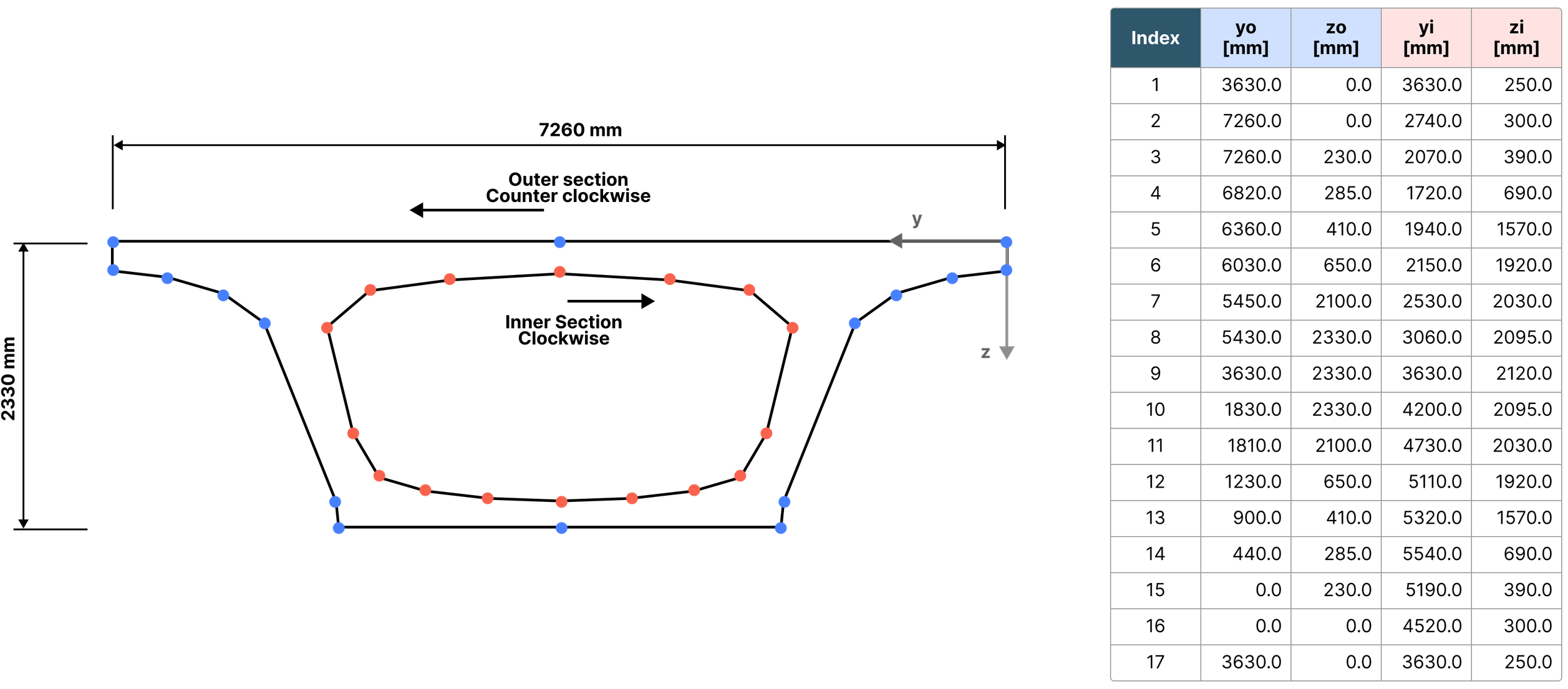
Figure 1. Example of a PSC box cross-section
(2) Section Property
Sectional properties are calculated using Green's theorem from the input coordinate data. The required section properties for the calculation are the area, second moment of area, and distance from the section's top edge to its centroid.
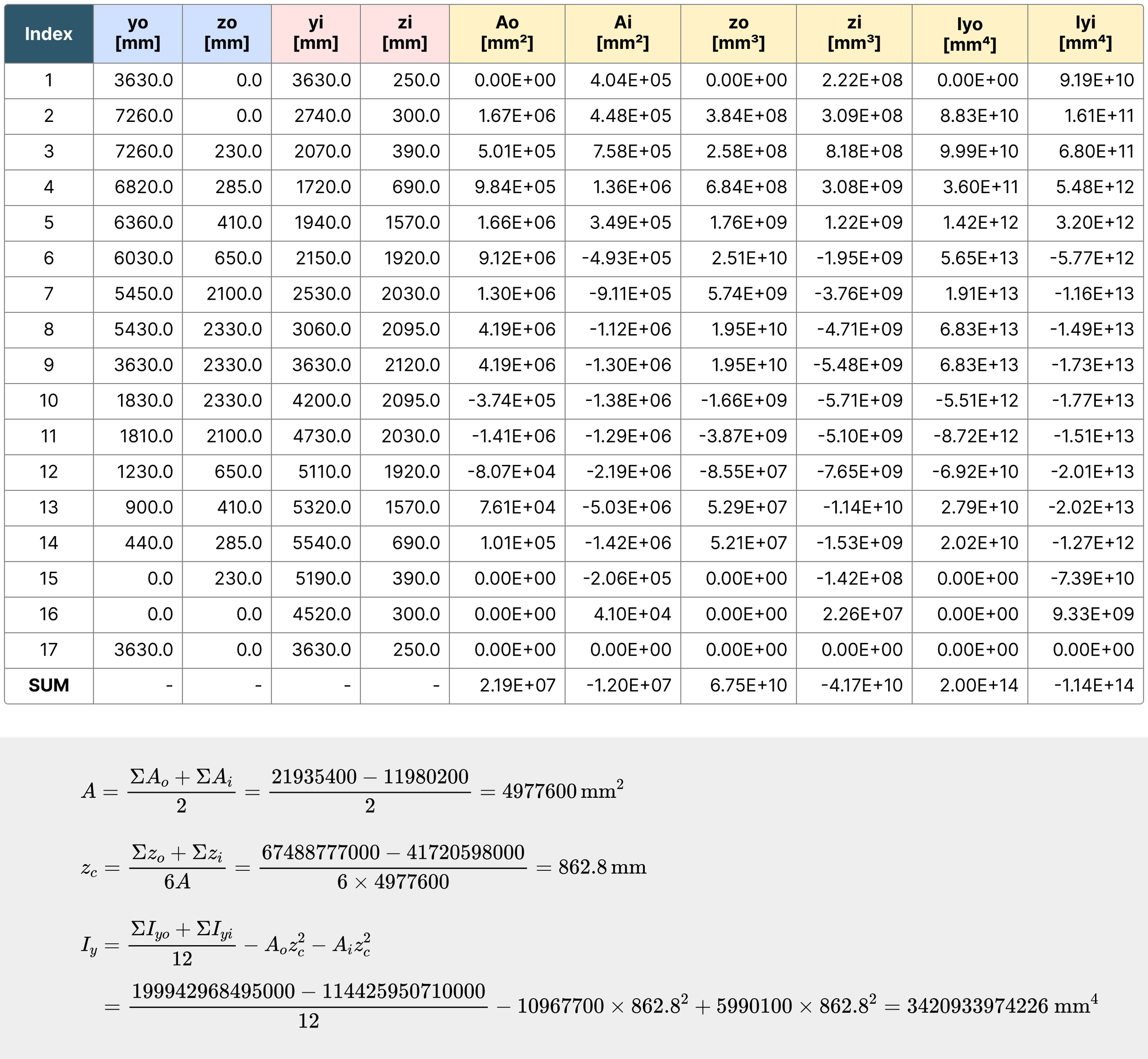
Figure 2. Cross-Sectional Properties
(3) Differential Temperature Load
AASHTO LRFD Heating case - Zone 3 is considered.
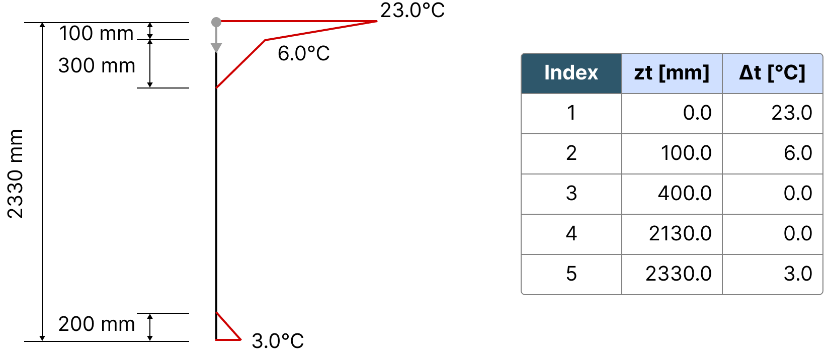
Figure 3. Differential Temperature load
(4) Section Coordinates and Temperature Gradient Load
To ensure the accuracy of the calculation, the change point of the temperature gradient load must be included. Therefore, the change point of the temperature gradient load was added to the cross-sectional coordinates, and the temperature gradient load was applied to each node.
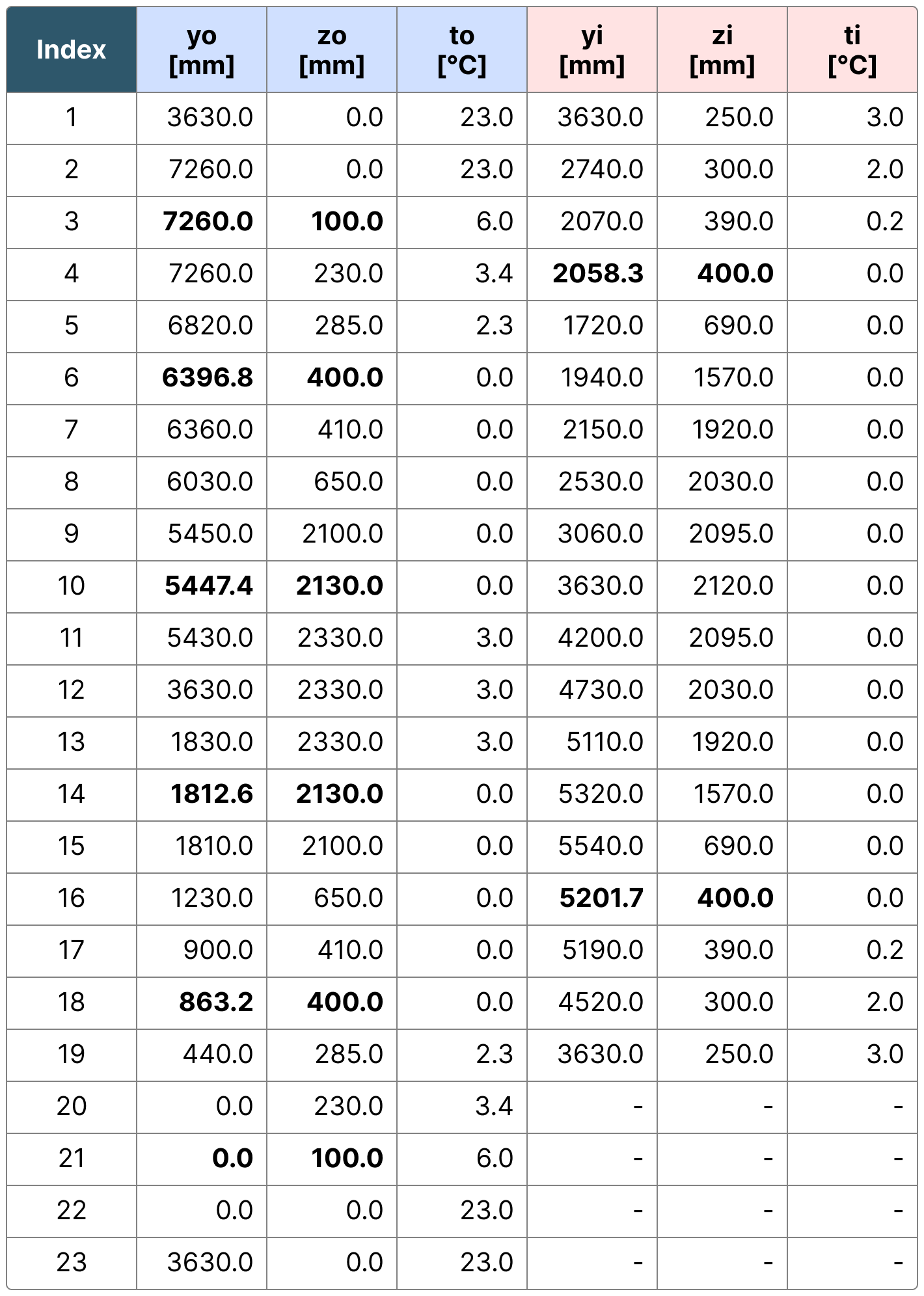
Figure 4. Temperature gradient load at Each node
(5) Restraint force
The restraint force can be calculated using the equation derived in section 3, but since the temperature and width vary linearly on the z-axis and y-axis, respectively, we can write linear equations in terms of z for temperature (t) and y for width (b) and substitute them into the equation. Therefore, the equation can be expressed as follows:

Figure 5. Equation of a straight line based on changes in width and temperature

Figure 6. The formula for calculating restraint force
Now, if we apply the formula for calculating restraint force that has been determined to each straight line and calculate it, we can obtain the following restraint force.
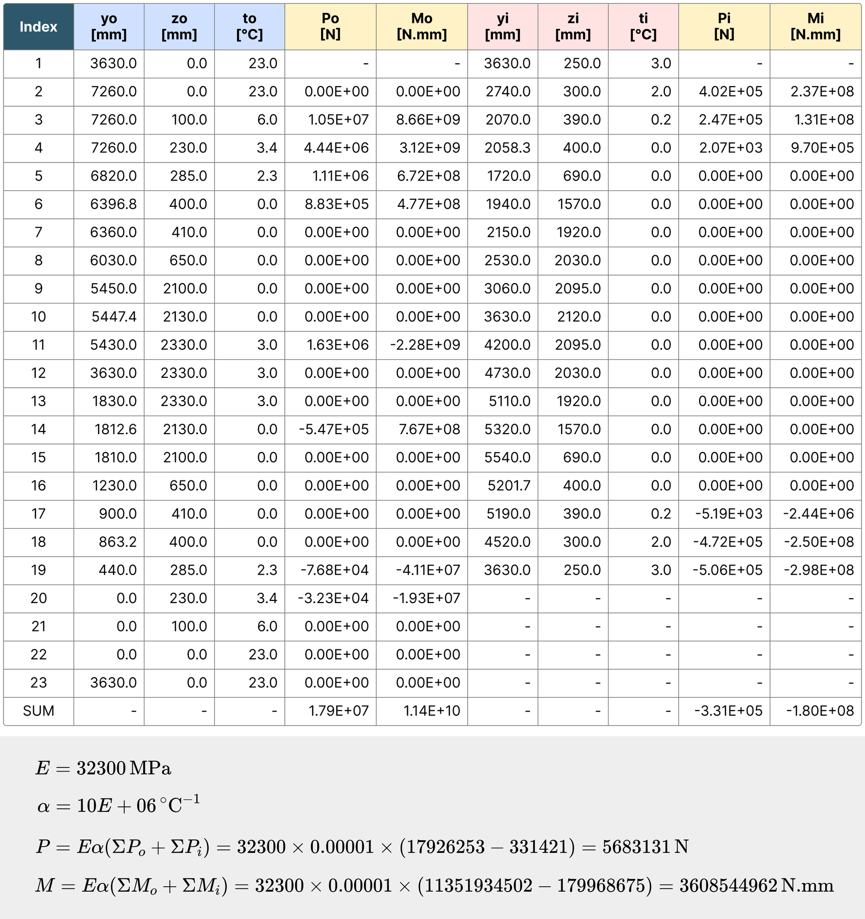
Figure 7. Restraint force
(6) Residual Stress
Using the calculated acceleration and temperature gradient load, the residual stress at each node is determined as follows.
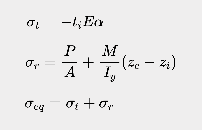
Figure 8. The equation for Residual Stress
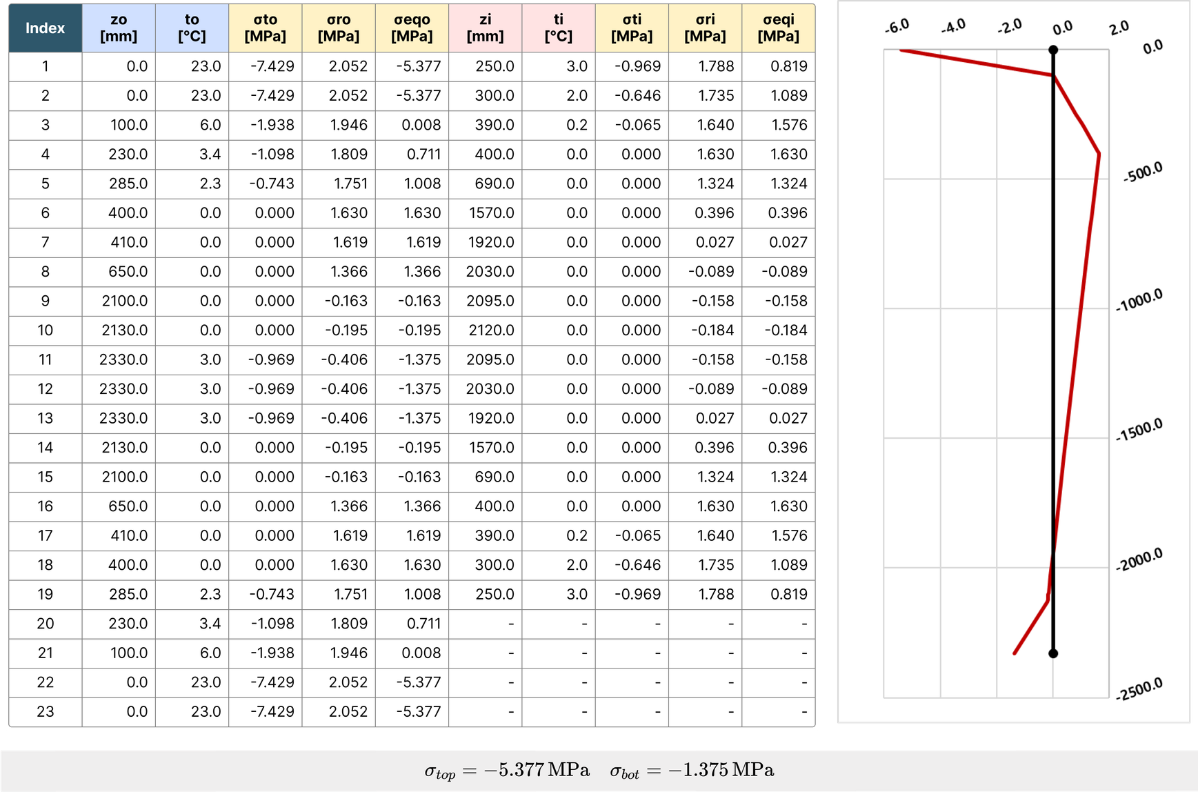
Figure 9. Residual Stress
(7) Calculation and Verification
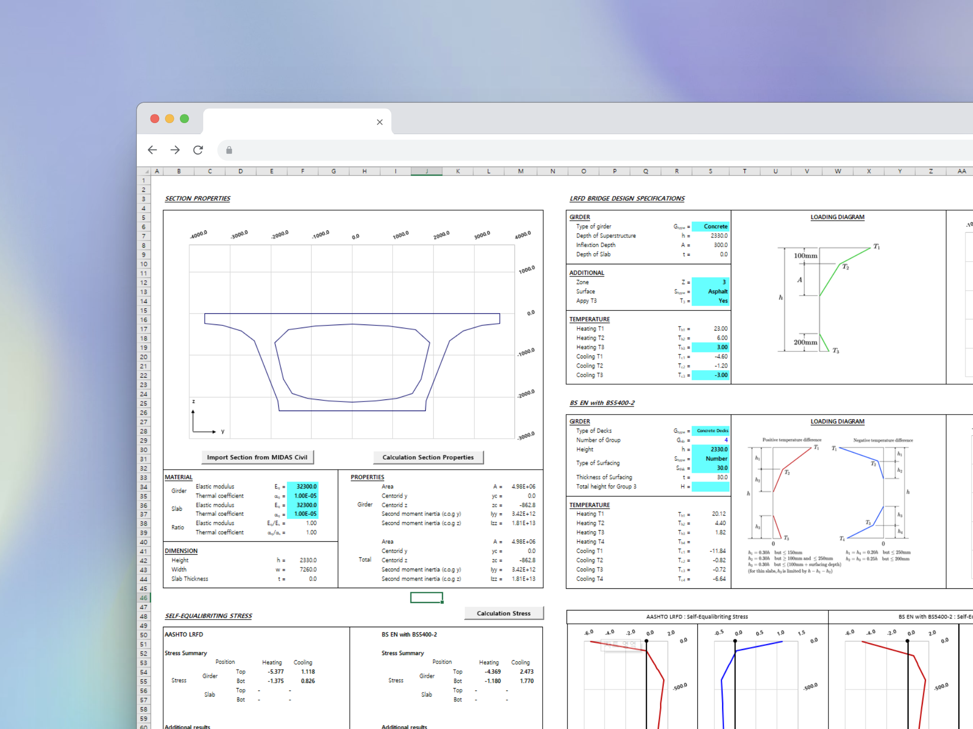
This is an Excel spreadsheet designed using VBA based on the formulas introduced above. It allows users to input the loads examined in Part 1/Part 2, calculates the residual stress accordingly, and generates a graph.
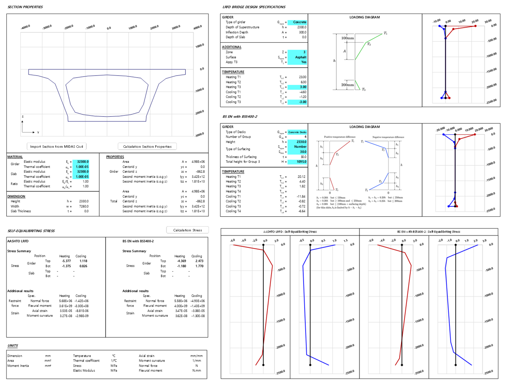
Figure 10. Sample Calculation
Now, let's verify the created spreadsheet. First, we will use the same cross-section as in the example, and the loads are defined as follows, and the results are shown in the spreadsheet accordingly.
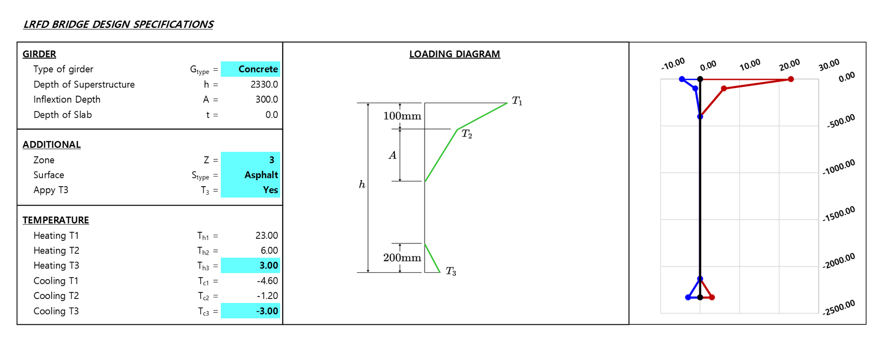
Figure 11. Calculation example for verification 1

Figure 12. Calculation example for verification 2
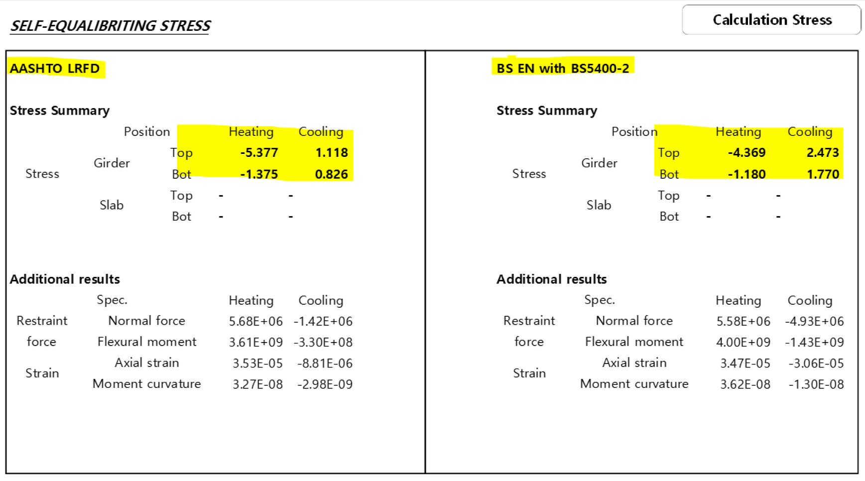
Figure 13. Calculation example for verification 3
The verification was performed using MIDAS CIVIL. The four simple spans with the same cross-section are created as shown in below the example and analysis is performed by applying the loads according to each design standard.
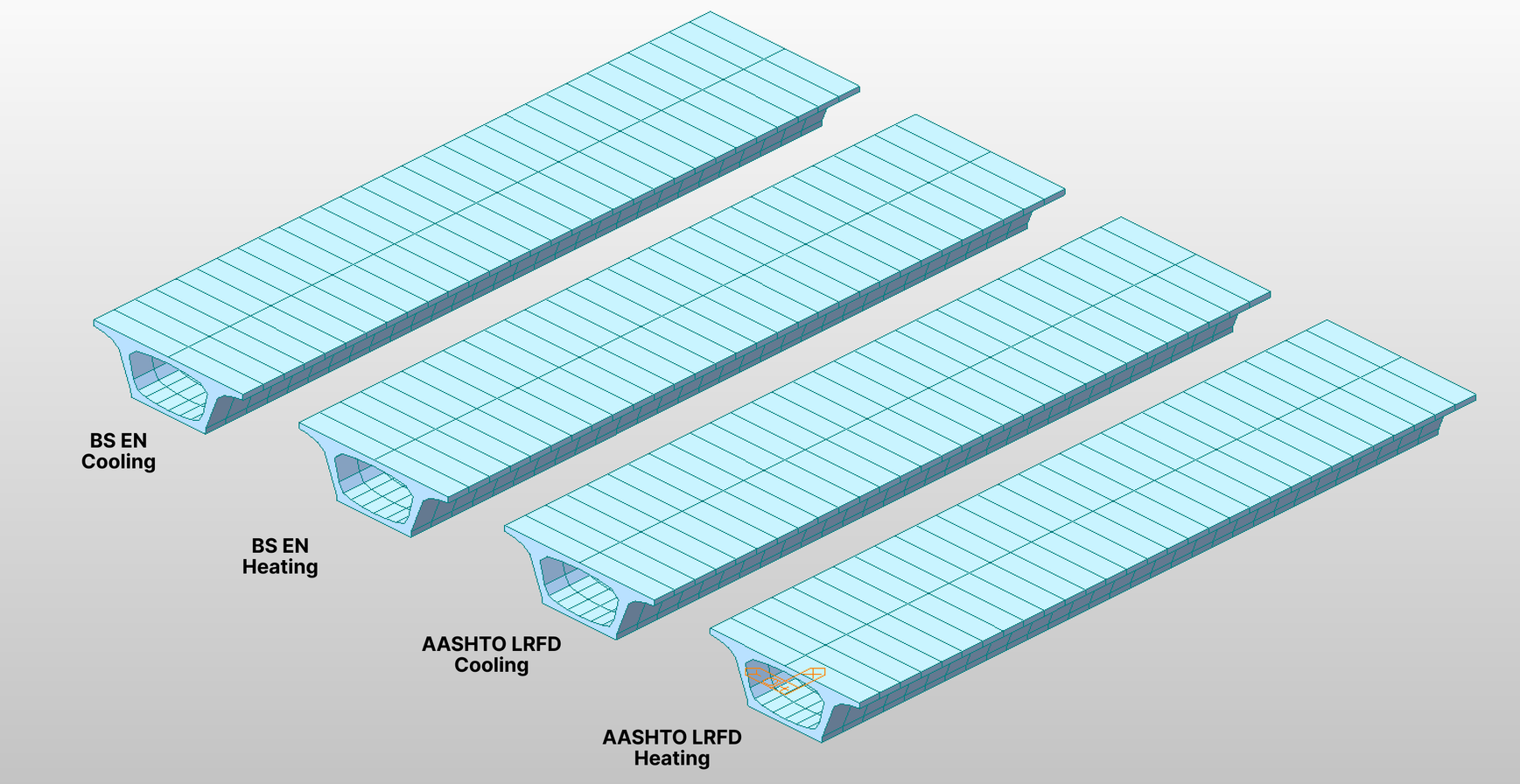
Figure 14. MIDAS CIVIL model for verification
The results are as follows.
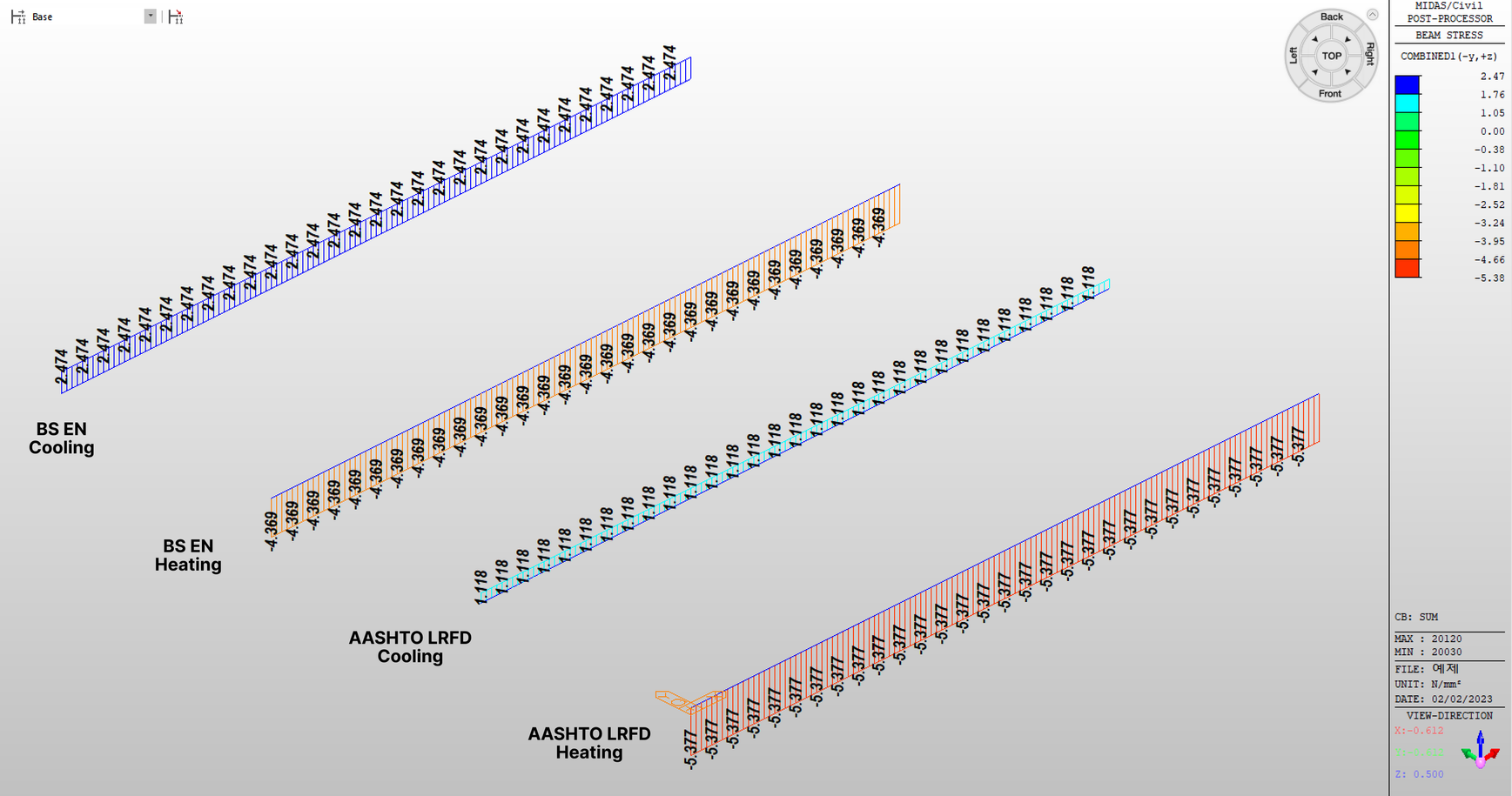
Figure 15. Top Stress - MIDAS CIVIL
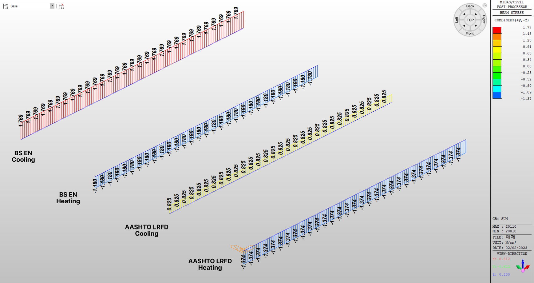
Figure 16. Bottom Stress - MIDAS CIVIL
As expected, the results show a 99% match with the values obtained from the spreadsheet.
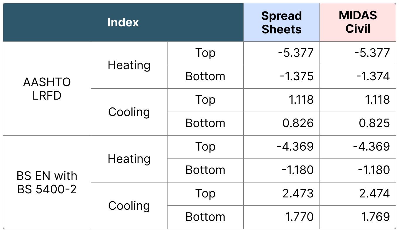
Figure 17. Values obtained from the spreadsheet
(8) Conclusion
We have examined the effect of temperature gradient loads on beams according to each design standard. Hopefully, this has provided a basic understanding of temperature gradient loads.
We can take this one step further by using these results to calculate axial strain and bending moment, which can then be converted into equivalent linear temperature loads. By doing so, we can predict the impact of temperature gradient loads in indeterminate structures.
In design, temperature loads are often included in most load combinations, and if the design is done within the range that does not allow tensile stress, the impact of temperature loads can be significant and cannot be ignored. I hope that the following article will be helpful in design.
#Temperature Gradient #Non-linear Temperature #Temperature Gradient #Temperature difference # Design Calculation #BS EN # AASHTO LRFD #BS 5400 #NCHRP #DMRB #CS 454
GOODNO, Barry J.; GERE, James M. Mechanics of materials. Cengage learning, 2020.HAMBLY, Edmund C. Bridge deck behaviour. CRC Press, 1991.
Would you like to use the Excel Spreadsheet in the content?
Submit the form below right away, and receive the file for calculating temperature gradient loads.
(Note! This spreadsheet requires access to the MIDAS CIVIL API for utilization.
If you have any inquiries regarding the CIVIL API, please feel free to leave a comment.)
👉🏻 Download Now